

For private-label bridle and tack brands
Custom Full-Cheek Bits from Your Drawings
Develop a full-cheek bit around your own mouthpiece, rod projections and bridle connections. We manufacture from customer drawings and support your logo, with the lateral rings and any keeper arrangement reviewed as part of the complete product. Show the geometry your brand needs, then agree the sample dimensions and contents before extending the size or mouthpiece range.
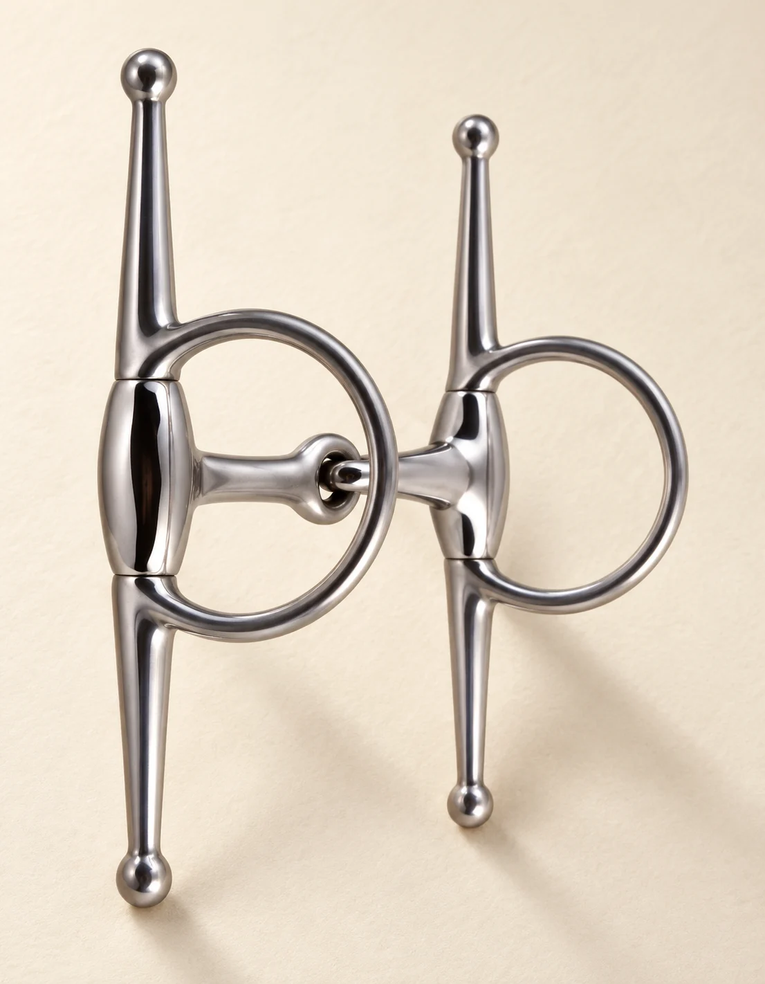
Build the Cheek and Mouthpiece as One Design
Keep the long cheeks and mouthpiece on one clear design. Relia manufactures its own full-cheek bits and accepts your drawings and logo. Material, dimensional, appearance and assembly-fit checks follow the rods, junctions and mouthpiece together, helping your brand retain the intended construction through sample changes.
Model configurations and dimensions
At Relia, we accept full-cheek bit drawings and customer-logo projects. A change in mouthpiece section, rod projection or ring junction belongs in the assembly drawing. Branding has its own artwork and position record, so the product geometry remains clear throughout development.
The model gives us real construction examples to discuss. Your drawing identifies the selected details, material requirements and any changes needed for the branded range.
Profile, joint or link, section and measured span.
Upper and lower projections, tips and lateral ring junction.
Artwork, position and the agreed marking approach.
Start with a Named Mouthpiece Construction
The full-cheek outline does not identify the mouthpiece. Our product range separates the examples below, including a copper-lozenge construction and a copper-wire double-twisted mouth. Choose the construction you intend to develop, then specify the exact component geometry and materials.
The full-cheek selection guide helps with ready-reference comparison. This page concerns manufacture from your own drawings.
| Model | Model construction | Development focus |
|---|---|---|
| 25736 | Stainless-steel full cheek; 125 mm snaffle mouth | Mouthpiece profile and single-joint assembly |
| 25445 | Full cheek; 5-inch Dr. Bristol mouth | Centre-piece profile and connections |
| 42736-CL | Three-piece snaffle mouth with copper lozenge | Centre material and both connecting interfaces |
| 25744 | 6-inch cheeks; 5-inch copper-wire double-twisted mouth | Separate mouthpiece construction and cheek drawing |
Draw the Projections from the Mouthpiece Junction
Use the mouthpiece junction as a named reference when defining the rod above and below it. Record the overall outline, each projection and the rounded end profile. An overall cheek length alone leaves the position of the mouthpiece unresolved.
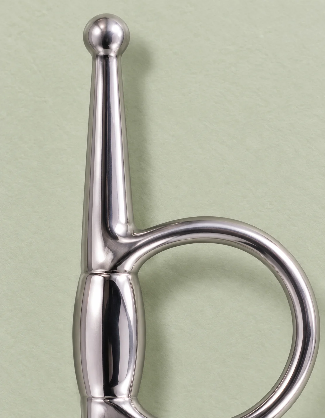
The 25736 detail below shows the upper rod and adjacent ring in the model configuration. For your design, add the dimensions and views needed to describe that relationship completely.
Include the Keeper and Bridle Interfaces in the Brief
If your retail version includes keepers, show their intended form, connection and supplied quantity. If the project is bit-only, identify that supply scope. The bridle interface and instructions should be reviewed with the intended configuration, rather than inferred from a model photograph.
A related BT0601 product shows a long-rod arrangement under its own product code. Keep the product range and current product references separately identified in the enquiry.
| Area | Buyer drawing or sample input | Sample review |
|---|---|---|
| Upper projection | Length, end profile and proposed keeper connection | Position, clearance and intended routing |
| Lower projection | Outline, length and rounded end requirement | Geometry and surface condition |
| Lateral ring | Opening, section and junction details | Attachment space and specified movement |
| Supplied scope | Bit-only or itemized accessories | Contents, identification and instructions |
Check Alignment and Ends after the Agreed Process
The mouthpiece junction is the reference for making the upper and lower cheek projections. We select the forming and any machining or welding operations required by the component design, followed by polishing, surface treatment and assembly. The rod ends, lateral rings and centre construction remain part of the same geometry.
We verify materials and dimensions, inspect appearance and check moving parts or assembly fit. Compare rod alignment, end condition, mouthpiece position and ring openings after the selected finishing work, using the complete sample and any agreed keeper arrangement. Keep logo placement and supplied contents with that revision so a size or artwork change remains clear.
- Resolve the drawingMouthpiece position, rod projections, junctions and materials.
- Agree the routeComponent-making, connections, surface finish and tooling scope.
- Inspect the featuresAlignment, ends, openings and connection surfaces.
- Review the assemblyDimensions, required movement, contents and appearance.
Specify the Centre Material and Both Connections
Factory model 42736-CL is listed with a three-piece snaffle mouth and copper lozenge. The centre and its two connections belong in the same development record. For your version, define the link outline, side profile and connection details alongside the arms and cheeks.
Keep a separate component material schedule. The jointed mouthpiece development guide provides the next step when the centre construction changes.
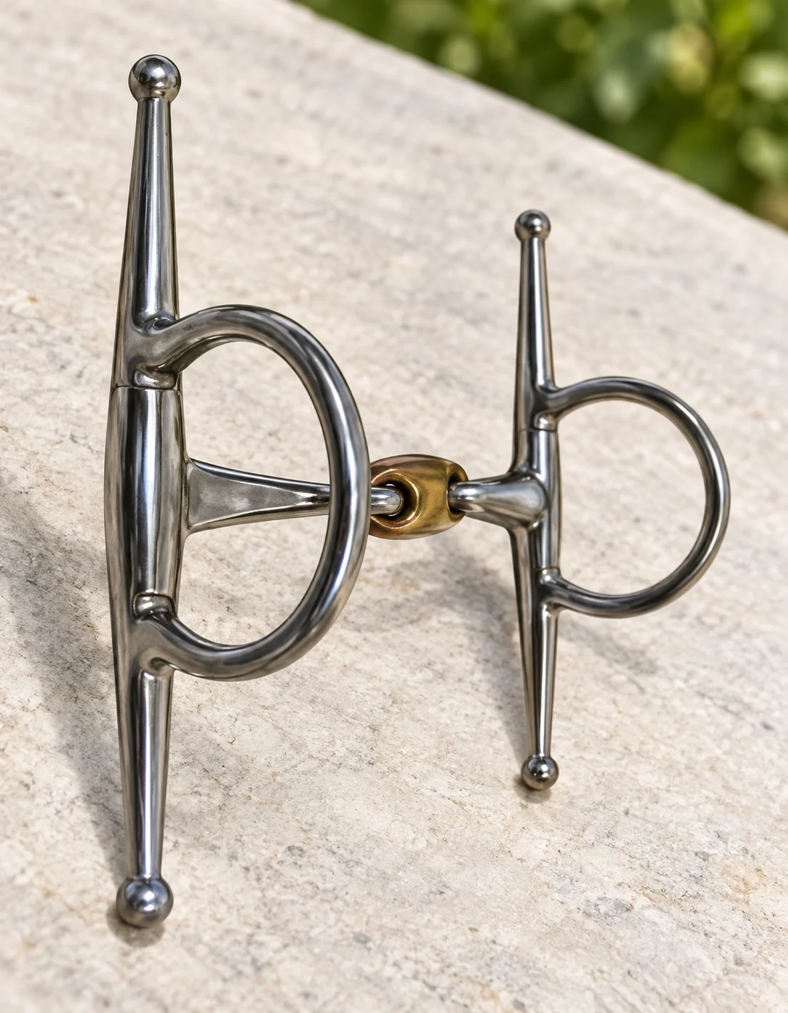
Keep Each Dimension with Its Model
The product range provides a defined example in 25736-S-125-14: 6½-inch cheeks, a 5-inch single-jointed mouthpiece and 14 mm thickness. Those fields describe that model configuration. Use the same level of detail for your custom drawing and its measurement endpoints.
When you develop another size or section, identify the changed dimensions explicitly. A similar cheek outline should not hide a different assembly revision.
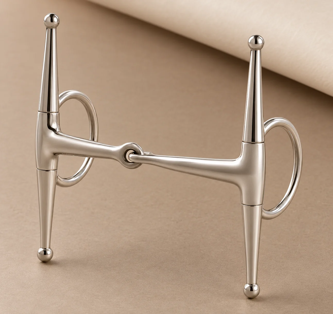
Release the Rod, Mouthpiece and Logo Revisions Together
Identify every branded version with its complete mouthpiece, measured cheek drawing and supplied contents. Add the accepted logo position and finish reference, then connect them to the physical sample. Later geometry changes can be reviewed against a clear baseline.
Plan the broader English-bit range · Develop a Pelham assembly · Agree the shared OEM project scope.
Rod projections, mouthpiece details and attachment drawings.
The accepted bit and any separately agreed keeper supply.
Logo artwork, location and physical finish sample.
Accepted revision, quantities, packing and current terms.
Select a Cheek Reference Before Drawing the Assembly
Use complete bit references to compare cheek forms, rings and mouthpiece constructions. When developing a full-cheek design, identify the exact reference and the feature you want to retain, then define the cheek and mouthpiece together on your drawing.
We use that drawing, your materials brief and logo artwork to focus the sample discussion on your intended assembly.
Define the Cheek and Mouthpiece Together
Identify the full-cheek shape and complete attachment arrangement.
State the construction, size and connected joint details.
Carry your materials, finish and logo through the same brief.
Send Your Full-Cheek Bit Drawing
Send the mouthpiece and cheek drawings, including the upper and lower projections, ring junctions and keeper scope. Add the component materials, logo artwork, planned range and quantities. We can review the design and agree a focused sample brief with you.
Send your project details · Learn about our factory business
Qingdao Relia Saddlery Co., Ltd.
info@reliasaddlery.com · +86 18561762631
Changjiang Road, Qingdao, Shandong, China
- Choose the productSend the model code, product link or your drawing.
- Describe your versionInclude the size, construction or appearance you need to discuss.
- Plan the next stepAdd quantity and destination, then agree the sample and quotation scope with us.