

For brands developing their own mouthpiece
Custom Jointed Mouthpieces and Bit Assemblies
Turn your mouthpiece design into a complete bit assembly with the centre, arms and cheek connections defined together. We manufacture from customer drawings and support your logo. Bring the component geometry and material requirements, then agree the sample's dimensions and movement checks with us. That keeps a centre-link change connected to the product your brand intends to supply.
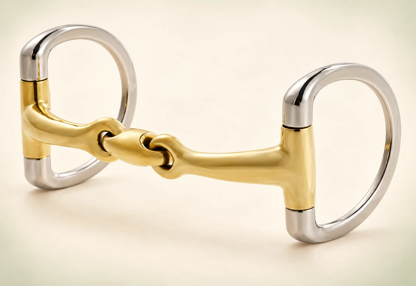
Develop the Connections as One Working Assembly
Make the connections work as one defined product. Relia manufactures horse bits and supports your assembly drawings and logo. We review the centre, adjacent links and cheeks together, checking materials, dimensions, appearance and assembled fit or movement so a component change remains clear throughout development.
Model configurations and dimensions
Compare the construction before assigning materials. The 3538 pair keeps a 66 mm cheek and 16 mm mouthpiece reference, while the named Alcopper version has its own mouthpiece material. Identify the centre and each connection on the drawing so the material choice stays attached to the assembly you want to develop.
For a branded assortment with an established construction, use the English-bit range guide. This page focuses on component development.
- Mouthpiece profileArm shape, section and curvature in the defined orientation.
- Centre connectionJoint or link geometry and the interfaces at each end.
- Outer connectionArm end, cheek or ring junction and attachment clearances.
- BrandingArtwork and position referenced to the agreed components.
Choose the Centre and Cheek Configuration Together
Choose a complete configuration before adapting the centre. The 3538 pair and 25700-427CL have distinct mouthpiece, centre and cheek details. Use the comparison below to explain the starting direction, then draw your actual connecting eyes, side profile and clearances. A centre change belongs in the whole assembly, not only a loose component sketch.
The mouthpiece selection guide · current oval-link D-ring product
| Model | Mouthpiece configuration | Cheek and size listing |
|---|---|---|
| 3538-16ALC/125 | Alcopper high-curved double joint | Eggbutt Dee, 66 mm rings; 5-inch width; 16 mm |
| 3538-16SS-125 | High-curved double joint | Eggbutt Dee, 66 mm rings; 5-inch width; 16 mm |
| 25700-427CL | Bronze oval-link double joint | Eggbutt, 70 mm flat rings; 5-inch width; 14 mm |
Make the Centre-Link Geometry Readable
The BT0319 reference connects two tapered arms to an oval centre through separate eyes. A custom link brief should define its outline, thickness and end connections together. An attractive top view can still leave the side profile and connection clearance unresolved.
Include the views needed to describe the full centre. We can then review the part and assembly details against the same version of your drawing.
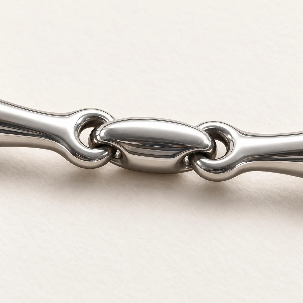
Assign Materials to Named Components
Give each component the material your product needs. The 3538-16ALC/125 uses an Alcopper mouthpiece, while 25700-427CL has a bronze oval-link construction. Identify the arms, centre and cheeks separately in your brief, then agree their actual material requirements in the quotation and sample.
| Component | Information to supply | Approval reference |
|---|---|---|
| Mouthpiece arms | Material, section and any core/outer-layer arrangement | Component drawing and accepted sample |
| Joint or centre | Material and connection dimensions | Named part and complete assembly |
| Cheeks or rings | Material, openings and junction details | Drawing plus agreed appearance |
| Logo area | Substrate, location and appearance requirement | Artwork position and physical marking sample |
Review the Route at Each Connection
The joint or centre-link design sets the component-making and connection requirements. We use the applicable forming, machining or welding operations for the chosen construction, followed by polishing, surface treatment and assembly. The arm ends, centre profile and outer junctions are defined together so the manufacturing discussion follows real mating features.
We verify materials and dimensions, inspect appearance and check moving parts and assembly fit. Compare the actual connection clearances, link orientation and accessible joint surfaces in the agreed positions of the complete sample. Keep those checks alongside the drawing and logo revision; dimensional acceptance and the qualified fitting assessment remain distinct parts of the product decision.
- Component definitionResolve geometry, material boundaries and any unfinished details.
- Production routeAgree the component-making and joining or assembly steps.
- Surface reviewSpecify the required finish and inspect edges and connection areas.
- Assembly reviewCheck the assembled dimensions and required movement.
Define the Section and Connection Materials
The BT0532 reference shows pale-looking sections, a small oval centre and exposed joining eyes. That appearance is useful for discussing component boundaries; it does not identify a cover or core material. Your specification should state the intended construction directly.
Where a design uses more than one material, show how each section ends and connects to the next. Keep the exact component list with the sample revision.
For a cast-component design, abrasive preparation and finishing must respect the connection shape defined in the drawing. We then check the finished assembly’s dimensions, appearance and moving-part fit against the agreed configuration.
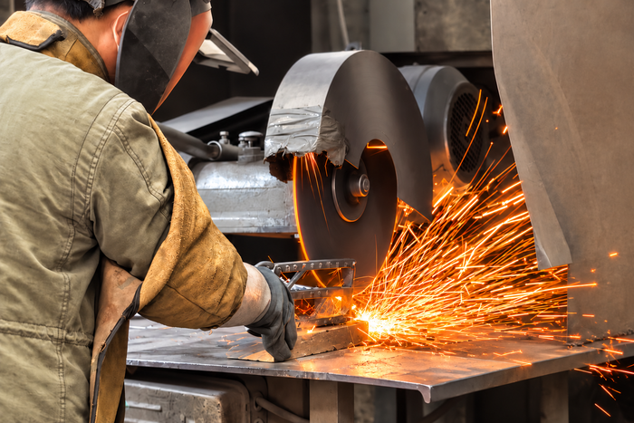
Check Movement on the Complete Sample
A complete sample lets both teams review the joint in the assembly it belongs to. Agree the measurement position, the movement to inspect and the required clearances. Check the connection surfaces in those positions, then record any change against the drawing revision.
Keep your intended-use and qualified fitting assessment separate from dimensional approval. A product photograph illustrates the configuration; it does not establish the effect on a particular horse.
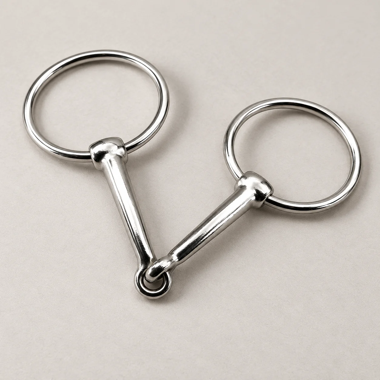
Release the Assembly, Artwork and Checks Together
The accepted product record should connect every component to the final assembly revision. Add the approved logo artwork, its location, finish reference and the agreed sample checks. A later link, material or cheek change then has an explicit place in the revision history.
Continue with the shared OEM project guide for tooling and commercial scope, or the Western shank-design guide when your design includes a different cheek and attachment system.
Named parts, materials and current detail drawings.
Complete configuration, measured interfaces and agreed movement.
Artwork revision, location and accepted appearance.
Sample approval, quantities, packing and current terms.
Discuss Your Mouthpiece and Assembly Drawing
Send the complete bit drawing and the detail views for its joint, centre and outer connections. Include your component material schedule, logo artwork and the requirements you want the sample to resolve. We can review the development scope and next sample step with you.
Send your development brief · Explore our product business
Qingdao Relia Saddlery Co., Ltd.
info@reliasaddlery.com · +86 18561762631
Changjiang Road, Qingdao, Shandong, China
- Choose the productSend the model code, product link or your drawing.
- Describe your versionInclude the size, construction or appearance you need to discuss.
- Plan the next stepAdd quantity and destination, then agree the sample and quotation scope with us.